Ocframe is a simple GNU octave package for structural analysis of 2D frames by using the Direct Stiffness Method (Matrix displacement method). Currently the basic needs are supported but this will change in the future.
For the moment all sorts of member loads and nodal loads are supported. The package will provide the displacements, the reaction forces and the member end forces. A plotting function is provided to plot the frame with node and member numbers. The structure with displacements can also be plotted.
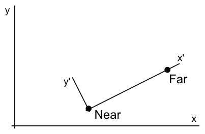
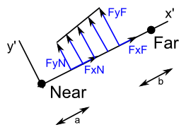
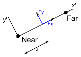
For the nodes and the members, care must be taken for the axes. The following images show the used coordinate systems and the conventions for the member forces. The local axes are always from the near node to the far node.


Examples of the usage are provided with the package. The units must be the same through all the input data. For example, if newtons (N) and meters (m) are required as output, the input units are N, Nm, N/m2, m4, ...
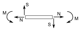
The output follows the coordinate systems which means that the displacements and the reactions are in global axes and member end forces in local axes. The exception are the internal forces for which the following convention is used:
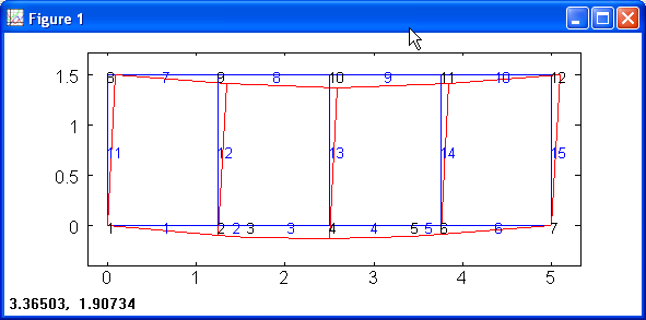
A few examples are include with the package. The third example consists of a large frame. When solved and plotted the graph looks like this:
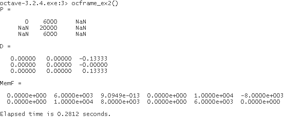
For example a normal beam with 3 supports (one each 4 meter), loaded with a distributed load of 4kN/m has the following input data:
The output looks as follows:
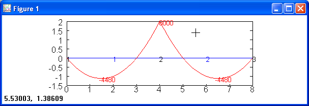
Adding the line PlotDiagrams(joints, members, dist, [], MemF, "M")
plots the moment diagram of the beam:
Ocframe is distributed as a GNU octave package and should be installed with pkg install. Put the .tar.gz where Octave can find it and issue the command pkg install filename.tar.gz
Ocframe can be loaded with the command pkg load ocframe. More details can be found in the GNU Octave manual.
Solves a 2D frame with the matrix displacement method for the following input parameters:
joints = [x , y, constraints ; ...]
constraints=[x , y, rotation] free=0, supported=1
members = [nodeN, nodeF, E, I, A; ...]
nodeloads = [node, Fx, Fy, Mz; ...]
loads on members:
dist = [membernum,FxN,FyN,FxF,FyF,a,b,local ; ...] for distributed loads where FxN and FyN are the loads on distance a from the near node (same with far node and distance b) local=1 if loads are on local axis, 0 if global
point = [membernum,Fx,Fy,a,local; ...] where Fx and Fy are the loads on distance a from the node near local=1 if loads are on local axis, 0 if global
Output is formated as follows (rownumber corresponds to node or member number):
Reactions = [Fx,Fy,Mz;...] where NaN it was a non supported dof
Displacements = [x,y,rotation;...]
MemF = [FxN, FyN, MzN, FxF, FyF, MzF; ...]
Plots a 2D frame (with displacements if needed) using the following input parameters:
joints = [x , y, constraints ; ...]
constraints=[x , y, rotation] free=0, supported=1
members = [nodeN, nodeF, E, I, A; ...]
Optional arguments:
D = [x,y,rotation;...] Displacements as returned by SolveFrame
factor= Scaling factor for the discplacements (default: 10)
This function plots the internal forces for all members. The force to be plotted can be selected with diagram which will be "M", "S" or "N" for the moment, shear or normal forces.
Input parameters are similar as with SolveFrame and PlotFrame.
This function returns the internal forces of a member for each position x. The member is divided in 20 subelements if the argument is not given. The used sign convention is displayed in the help file.
Input parameters are similar as with SolveFrame and PlotFrame with extra arguments:
membernum = Number of the member to calculate
divisions = Number of divisions for the member
Solves a 2D frame with the matrix displacement method for the following input parameters:
joints = [x , y, constraints ; ...]
constraints=[x , y, rotation] free=0, supported=1
members = [nodeN, nodeF, E, I, A; ...]
loadcases is a struct array with for each loadcase the fields
- nodeloads = [node, Fx, Fy, Mz; ...]
- dist = [membernum,FxN,FyN,FxF,FyF,a,b,local ; ...]
- point = [membernum,Fx,Fy,a,local; ...]
input is as for the function SolveFrame.
Output is a struct array with the fields: Displacements, Reactions and MemF
(output formated as for the function SolveFrame.)
Future releases might include the following features:
In the far future calculations in 3D might be an option.
I have been thinking about a full rewrite of the existing code in Java or Python. I really do not know what the best choice is because each language has pros and contras. Octave is an easy language to write code but the package will not be suitable for use in a bigger piece of software (e.g. steel frame calculation with full section analysis for the Eurocodes). Code in Python or Java could be made in the object oriented way and be much more flexible for use and adaptation. Your opinion is welcome here
Ocframe was written during a FEM course and finished as an Octave package in the hope that it will be usefull for other people. Although care has been taken to test all the functions and detect the bugs, some bugs may still exist. If you should happen to detect any, please report them on the sourceforge project page.